
hi,
I am new to this mechanical and like to study. please help me on this.
I want to check the valve clearance, but I am not clearly sure whether I am right or wrong..
I position the TDC mark as service manual
![]()
that means the piston #1 & #4 are in position of TDC right?
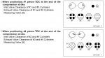
how to get this below in order to get measurement/reading of valve clearance?
![]()
I am new to this mechanical and like to study. please help me on this.
I want to check the valve clearance, but I am not clearly sure whether I am right or wrong..
I position the TDC mark as service manual
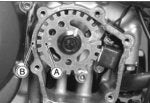
that means the piston #1 & #4 are in position of TDC right?
how to get this below in order to get measurement/reading of valve clearance?


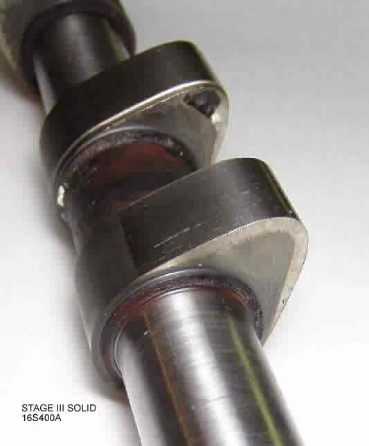
") Not sure why I remember it being more descriptive than it is, guess I just understood what needed to be done. But, like I said the key is that the lobe be pointing up on the valves that you are measuring. They should not be turned down to where they are pushing the valve.
Not sure why I remember it being more descriptive than it is, guess I just understood what needed to be done. But, like I said the key is that the lobe be pointing up on the valves that you are measuring. They should not be turned down to where they are pushing the valve.